Table of Contents
The core component within Morovia Barcode DLL is a powerful, versatile control, also referred as Barcode Object throughout this manual. This control does not only create barcode image, but also human readable text and comment. It allows flexible layout of these components. This chapter gets you familiar with the basic concepts necessary to work with the control.
To simplify application design, this manual categorizes the control usage into two design modes: barcode design mode and label design mode. Barcode design mode is for those whose tasks emphasize on the barcode image rather than the “label”. Under barcode design mode, the size of the working area is not fixed and can expand or shrink necessarily to hold the complete barcode label, including quiet zones, comments and margins. On the contrary, under label design mode the working area is predecided and will not expand or shrink. The barcode portion can expand or shrink but it will not impact the overall label space.
The property AutoLabelSize determines
the design mode. If AutoLabelSize is TRUE,
you are working under the barcode design mode, where the
label size is not fixed. If more data is encoded into
the barcode, or you add more text into the comment, the
overall size increases. Under barcode design mode,
the properties LabelWidth and LabelHeight are read only and
you can not change them; rather, you can increase or decrease
the overall drawing area by changing the margin, barcode data,
or comment size.
On the other side, when AutoLabelSize is FALSE, the working
area is pre-determined by the properties LabelWidth and LabelHeight.
You can modify the natural size by modifying these two properties.
Any drawings outside the predefined area are clipped.
In most cases you probably do not need the
zooming feature. We highly recommend that you make sure
that the ZoomRatio equals to 1.0 when you print the barcode.
This zooming feature is provided for creating comprehensive
labeling applications.
To avoid confusion, this manual defines two sizes here: natural size and display size. The natural size is the size of the control itself without scaling. The display size is the natural size multiplies the zoom ratio.
There are two types of zooming: programmed and interactive.
In the first scenario, the control size is determined by
the actual size and ZoomRatio.
The program
changes the control size by programmatically modifying
the ZoomRatio. In the latter case, the user drags on the
tracker box to the size desired, and the object responds by
drawing itself to the maximum extent in the box specified.
Although you can switch from one to the other zooming mode,
you can not have both at the same time. The zoom mode is
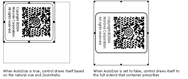
determined by property AutoSize:
if this property is set
to TRUE, the control determines the size and you can
programmatically zoom the control by setting the ZoomRatio
property to an appropriate value. If AutoSize is set to FALSE, the container takes the charge and the control
redraws itself every time the container's size changes
(with several extra lines of code you will be able to achieve
the interactive dragging effect). Under the interactive
mode you can not set ZoomRatio property;
it becomes read-only.
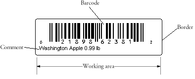
There are a couple of elements appearing in the working area - barcode, human readable, margins and comment. Since the working area includes not only the barcode image, in this manual we use the term “label” or “the working area” to refer to the whole drawing.
The whole drawing (label) consists of three major components, as you can see from the illustration below: (1) the bounding borders surrounding the label; (2) symbol margins surrounding the symbol area; (3) the symbol area, which includes the barcode, human readable and the comment. Furthermore, the whole symbol area can be divided into two parts: (1) the barcode. A barcode can also have a human readable text. You can add extra white spaces surrounding the barcode, a.k.a. Quiet Zones. The human readable text can appear on the top of the barcode, or on the bottom, or does not appear at all. (2) the comment. A comment consists of one or more text paragraphs. Same as the human readable text, the comment can be placed on the top, on the bottom of the image, or does not appear at all.
Three properties control the appearance of the borders: BorderColor, BorderStyle and BorderWidth.
To turn off the border, set BorderWidth to 0 or
BorderStyle to mbxBorderStyleNone.
The BorderWidth property does not affect the overall size.
The border aligns its outer edge to the boundary
of the working area.
The borders are turned off by default in Barcode DLL 4.0.
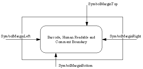
The margin properties control the marginal space around the symbol area (barcode and comment). There are four symbol margin properties: SymbolMarginLeft, SymbolMarginRight, SymbolMarginTop and SymbolMarginBottom, which define the margin spaces in the four directions respectively.
By default, Barcode DLL adds 100 mils (2.54 mm) margins surrounding the symbol. To modify the symbol margins, set the four symbol margin properties to appropriate values.
The symbol area consists of two components: barcode and comment. The barcode element comprises a barcode image, an optional human readable text and optional quiet zones. The human readable can be placed on the top or the bottom of the barcode element, or does not display at all.
The comment element contains one or more text paragraphs.
The barcode part is always placed in the center of the working area (if there is no rotation at all). The vertical position is determined by two comment margin properties: CommentMarginTop and CommentMarginBottom. If the comment is placed on top of the barcode area, the distance from the bottom edge of the comment to the top edge of the barcode is CommentMarginBottom; otherwise the top edge of the barcode is the top boundary of the symbol. Similar calculation applies to the case when comment is placed on the bottom.
The vertical position of the comment depends on the
CommentOnTop property. When this property is set to TRUE,
the distance from the top edge of the comment to the bottom of
the symbol is expressed in CommentMarginTop.
The distance from the bottom edge of the comment box
to the top of the barcode is expressed in CommentMarginBottom.
The design mode affects the horizontal placement of the comment element. Under label design mode, where the label size (working area) is fixed regardless of the symbology and encoding data, the property CommentMarginLeft measures the distance from the left edge of the symbol to the left edge of the comment box. The CommentMarginRight property measures the distance from the right edge of the symbol to the right edge of the comment box. The calculation is somehow different under barcode design mode: Under barcode design mode, the CommentMarginLeft measures the distance from the left edge of the comment text box to the left edge of the barcode, and CommentMarginRight measures the distance from the right edge of the barcode to the right edge of the comment box.
A barcode consists of two elements. In linear symbologies, the dark element is called Bar, and the white element is called Space. In two dimensional symbologies, both elements are referred as module - the dark (black) module and the light (white) module.
Most linear symbologies allow 1 or 2 widths. In the first scenario, the width of an element could be 2, 3 or 4 times of the width of the narrowest element. In the second scenario, two widths are defined, one for the wide elements and one for the narrow elements. The width of the wide element divided by the width of the narrow element is called NarrowToWideRatio. In both cases, the overall barcode length achievable depends on how small the width of the narrowest element can go. The width of the narrowest element is also referred as X dimension (sometimes abbreviated as “X Dim”). In Barcode DLL you can set the X dimension through property NarrowBarWidth.
The length of the X dimension is usually very small. The industry measures the X dimension in 1/1000 inch units, called mils. A mil equals to 1/1000 inch. Nowadays millimeters are also used in some cases. Due to the legacy that most barcodes have so far been produced by specialized barcode printers and most of those barcode printers have a low resolution at 203-dpi, the X dimension is often integral times of the pixel width on a 203-dpi printer - a typical requirement is 15 mils (the width of three printer pixels on a 203 dpi printer).
The smallest width that a barcode reader can distinguish is called scanner resolution. Today, most commercial scanners have a resolution around 10 mils, meaning that they won't be able to read the barcodes with X dimension at 5 mils. High resolution scanners can go as low as 3~5 mils.
Barcode DLL supports two measurement units:
mils and high metric (1/1000 cm). The user can select
whichever convenient to use. On the other side,
although you can set whatever values you desire,
you may not be able to achieve the accuracy because of
the limitations of the device. You can not print on 1.5
pixels. If you plan to create barcodes on low-resolution
devices, such as fax transmission, screen or thermal printers,
refer to Chapter 6, Working with Low Resolution Devices.


